En
En  Sv
SvIn-depth study
Ohm’s law
Skyllermarks has, throughout the years, informed you as a boat owner about what you can gain by taking care of your electrical system. We often talk about what you should do and what you get, but not why it actually works. We are going to review some high school physics for anyone wondering why you can get double charging.
Very briefly, we can refer everything to Ohm’s law, but without further explanation, no one becomes any happier from that.
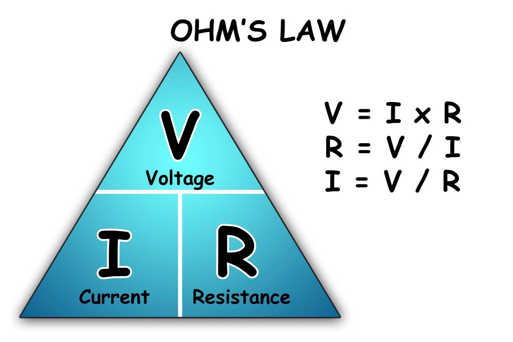
Ohm’s law describes how the current (I) varies with an applied voltage (U) and the resistance (R) over which the voltage is applied. Double the voltage gives double the current if the resistance is unchanged. Double the resistance gives half the current if the voltage is constant.
Practical Electrical Handling in Boats
It is a common misconception that charging in a boat takes place at 14.4 volts. Because if we look at the charging circuit, we see the following:
The battery, as is well known, has its own voltage, a counter‑voltage. Counter‑voltage is the voltage the battery shows if we measure it just after switching off the engine. The battery’s counter‑voltage cancels out a large part of the generator’s voltage, so we are actually left with approximately 14.2 – 12.5 = 1.7 V. We therefore have 1.7 volts available. That is as much as a flashlight battery, yet we still want to get fifty amperes!
The maximum UG is determined by the generator’s regulator (usually 14.1–14.4 V), and U is determined by the state of charge of the battery.
If UG – UB are fixed values, then we must ensure that the battery’s internal resistance (RB) is low. If RB is low, the battery is said to have good charge acceptance. The battery’s resistance is determined by its chemical and physical construction. A starter battery has very good charge acceptance, a leisure battery somewhat poorer, and a GEL battery has the poorest acceptance.

No ideal circuit
The above reasoning assumes that all energy is transferred without loss from the generator to the battery, which of course is not the case. In practice, we must introduce a resistance, RK, which represents the resistance in cables, connections, isolator diodes, and similar components.
Assume that we have a situation where the generator is at its maximum of 14.2 V. It is still charging at 50 A, and the battery is half full and provides a counter‑voltage of 12.8 V. The net voltage that overcomes the battery’s RB is then 1.4 V. If the resistance in cables and connections, RK, causes a voltage drop of 0.7 V, then only half of that—0.7 volts—remains.
This is not an unreasonable assumption. Our measurements show that a standard isolator diode on its own can add a voltage drop of 0.7 volts. Add some losses in cables and connections, and it becomes clear that both the charging voltage and, in turn, the charging current can be more than halved.