FAQ Alternator questions

Home / Wired and Inspired / Charging & Alternators / FAQ Alternator questions

Frequently asked questions about alternator and charging systems

Do you have questions about how your alternator works, which cables are needed, or how the charge regulator affects the voltage? Here you will find answers to the most common questions about the installation, wiring, and maintenance of alternators. Whether you are wondering about [B-], [D+], or how to use a [TWC regulator], we have gathered all the information you need.

Not finding what you were looking for? Get in touch with us!

Why are there so many cables on my generator?

The alternator is often used as a bus bar.
The engine requires electrical power for both instruments and sensors.
The starter motor is frequently used as a bus bar for various electrical loads.

If no B− terminal is provided, connect the negative cable directly to the alternator housing.

The alternator’s voltage regulator limits the maximum output voltage by controlling the amount of current flowing through the rotor field winding.

Three of them; B+, B- and D+.

No, the alternator regulator cannot switch down to maintenance charging. The regulator’s job is to make sure that the alternator maintains 14.4 V.

No, the batteries regulate the charge themselves by constantly increasing the resistance to charge during the charging process.

A 50 A alternator will overheat and fail if the current becomes significantly higher than 50 A.
For this reason, the alternator regulates the magnetization of the rotor to prevent this from occurring.
In addition, the voltage regulator limits the system voltage to typically no more than 14.4 V.

TWC is an alternator regulator designed to compensate for undesired voltage drop. Volvo Penta offers a corresponding unit. However, neither the TWC nor Volvo Penta’s equivalent can switch down to a maintenance/float charge mode.

Connect the sense wire from the regulator to the alternator B+ terminal, and run the cables from B+ and B− to the battery with a maximum total voltage drop of 0.1 V, as usual.

The D+ terminal shall cause the relay to engage if and only if the ignition is switched on.

Few alternators are true two‑pole units. Proper two‑pole alternators and starter motors are expensive.

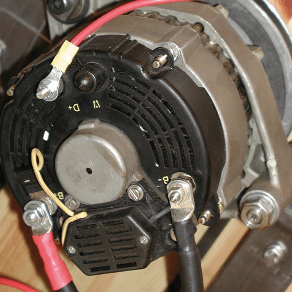
The most common design is that B− is connected directly to the alternator housing. In this case, B− is not isolated from the engine block (chassis ground).
If no dedicated B− terminal is provided, use any bolt on the alternator housing or one of the alternator mounting bolts for the negative connection.
However, make sure that the alternator is not mounted using rubber bushings for vibration isolation. If rubber isolators are used, it is possible to end up on the wrong side of the insulating bushings, resulting in no electrical ground connection at all.

Turn the ignition key on. Measure at the alternator: D+ must have voltage when the ignition key is ON, but no voltage when it is switched OFF.

Alternatively, connect one terminal of the battery isolator relay to the battery negative (−). Attach a test lead to the relay’s other terminal and probe the alternator’s various connections. When you touch the test lead to D+, the relay should click/energize if and only if the ignition is ON.

More tips & tricks

What connections are there on the alternator?

Why is the charging performance so poor?

Solar panels

Lower risk with higher voltage

Shore power charger or not?

Can I leave the ignition on while listening to the radio?

How does the charge indicator lamp work?

How does generator charging work?

Make your own alternating current

Get the most charge for your money

Is the alternator not working?

Do you have another question?

Didn’t find the right answer to your question? Contact us via the form below and we will get back to you!